Update Required
To play the media you will need to either update your browser to a recent version or update your
Update Required
To play the media you will need to either update your browser to a recent version or update your
RSLogix500 Inserting Instructions
Update Required
To play the media you will need to either update your browser to a recent version or update your
RSLogix500 Opening a File
Update Required
To play the media you will need to either update your browser to a recent version or update your
RSLogix500 Creating a Project
Update Required
To play the media you will need to either update your browser to a recent version or update your
RSLogix500 Instruction Comments
Update Required
To play the media you will need to either update your browser to a recent version or update your
RSLogix500 Rung Comments Page Titles
Update Required
To play the media you will need to either update your browser to a recent version or update your
RSLogix500 Inserting Branches
Update Required
To play the media you will need to either update your browser to a recent version or update your
RSLogix500 Program Organization, Part 1 - Overview
Update Required
To play the media you will need to either update your browser to a recent version or update your
RSLogix500 Program Organization, Part 2 - Examples
Update Required
To play the media you will need to either update your browser to a recent version or update your
Update Required
To play the media you will need to either update your browser to a recent version or update your
RSLogix500 View Properties
Update Required
To play the media you will need to either update your browser to a recent version or update your
Update Required
To play the media you will need to either update your browser to a recent version or update your
RSLogix500 Online Offline
Update Required
To play the media you will need to either update your browser to a recent version or update your
RSLogix500 Dowloading and Uploading
Update Required
To play the media you will need to either update your browser to a recent version or update your
RSLogix500 Processor Modes
Update Required
To play the media you will need to either update your browser to a recent version or update your
RSLogix500 Processor and Cards
Update Required
To play the media you will need to either update your browser to a recent version or update your
RSLogix500 Introduction to Faults
Update Required
To play the media you will need to either update your browser to a recent version or update your
RSLogix500 Indirect Addressing
Update Required
To play the media you will need to either update your browser to a recent version or update your
RSLogix500 Indirect Addressing Faults
Update Required
To play the media you will need to either update your browser to a recent version or update your
RSLogix500 Handling Faults
Update Required
To play the media you will need to either update your browser to a recent version or update your
Update Required
To play the media you will need to either update your browser to a recent version or update your
RSLogix500 Custom Data Monitor
Update Required
To play the media you will need to either update your browser to a recent version or update your
RSLogix500 I/O Configuration
Update Required
To play the media you will need to either update your browser to a recent version or update your
RSLogix500 Advanced Diagnostics
Update Required
To play the media you will need to either update your browser to a recent version or update your
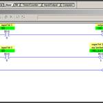
RSLogix500 Instructions OTL OTU, Part 1
Update Required
To play the media you will need to either update your browser to a recent version or update your
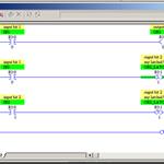
RSLogix500 Instructions OTL OTU, Part 2
Update Required
To play the media you will need to either update your browser to a recent version or update your
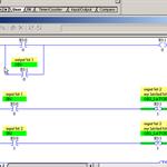
RSLogix500 Instructions OTL OTU, Part 3
Update Required
To play the media you will need to either update your browser to a recent version or update your
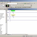
RSLogix500 Instructions, OTE
Update Required
To play the media you will need to either update your browser to a recent version or update your
RSLogix500 Instructions, XIC XIO
Update Required
To play the media you will need to either update your browser to a recent version or update your
RSLogix500 Instructions, ADD
Update Required
To play the media you will need to either update your browser to a recent version or update your
RSLogix500 Instructions, COP
Update Required
To play the media you will need to either update your browser to a recent version or update your
RSLogix500 Instructions, CPT - Part 2
Update Required
To play the media you will need to either update your browser to a recent version or update your
RSLogix500 Instructions, CTU CTD - Part 1
Update Required
To play the media you will need to either update your browser to a recent version or update your
RSLogix500 Instructions, CTU CTD - Part 2
Update Required
To play the media you will need to either update your browser to a recent version or update your
RSLogix500 Instructions, CTU CTD - Part 3
Update Required
To play the media you will need to either update your browser to a recent version or update your
RSLogix500 Instructions, CPT - Part 1
Update Required
To play the media you will need to either update your browser to a recent version or update your
RSLogix500 - Comparison - Part1
Update Required
To play the media you will need to either update your browser to a recent version or update your
RSLogix500 - Comparison - Part 2
Update Required
To play the media you will need to either update your browser to a recent version or update your
RSLogix500 Instructions, DIV
Update Required
To play the media you will need to either update your browser to a recent version or update your
RSLogix500 - FIFO - FFL and FFU - Part 1
Update Required
To play the media you will need to either update your browser to a recent version or update your
RSLogix500 - FIFO - FFL and FFU - Part 2
Update Required
To play the media you will need to either update your browser to a recent version or update your
RSLogix500 Instructions, FLL
Update Required
To play the media you will need to either update your browser to a recent version or update your
RSLogix500 Instructions, JMP and LBL
Update Required
To play the media you will need to either update your browser to a recent version or update your
RSLogix500 Instructions, Masking and MEQ
Update Required
To play the media you will need to either update your browser to a recent version or update your
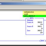
RSLogix500 Instructions, MUL
Update Required
To play the media you will need to either update your browser to a recent version or update your
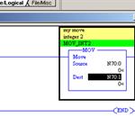
RSLogix500 Instructions, MOV
Update Required
To play the media you will need to either update your browser to a recent version or update your
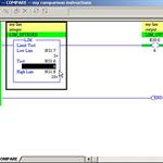
RSLogix500 Instructions, LIM
Update Required
To play the media you will need to either update your browser to a recent version or update your
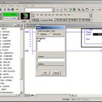
RSLogix500 Instructions, NEG
Update Required
To play the media you will need to either update your browser to a recent version or update your
RSLogix500 Instructions, OSR
Update Required
To play the media you will need to either update your browser to a recent version or update your
RSLogix500 Instructions, RTO
Update Required
To play the media you will need to either update your browser to a recent version or update your
RSLogix500 Instructions, SQO sequencer - Part 1 of 3
Update Required
To play the media you will need to either update your browser to a recent version or update your
RSLogix500 Instructions, SQO sequencer - Part 2 of 3
Update Required
To play the media you will need to either update your browser to a recent version or update your
RSLogix500 Instructions, SQO sequencer - Part 3 of 3
Update Required
To play the media you will need to either update your browser to a recent version or update your
RSLogix500 Instructions, SUB
Update Required
To play the media you will need to either update your browser to a recent version or update your
RSLogix500 Instructions, TOF
Update Required
To play the media you will need to either update your browser to a recent version or update your
RSLogix500 Instructions, JSR and RET
Update Required
To play the media you will need to either update your browser to a recent version or update your
RSLogix500 Shift registers
Update Required
To play the media you will need to either update your browser to a recent version or update your
RSLogix500 Instructions, SQR
Update Required
To play the media you will need to either update your browser to a recent version or update your
RSLogix500 Instructions, TON - Part 1
Update Required
To play the media you will need to either update your browser to a recent version or update your
RSLogix500 Instructions, TON - Part 2
Update Required
To play the media you will need to either update your browser to a recent version or update your
RSLogix500 Instructions, TON - Part 3
Update Required
To play the media you will need to either update your browser to a recent version or update your
Introduction to Ladder Logic